A Simple Power Monitoring Idea
I’ve been thinking about how I, and others, can reduce the carbon intensity of our electricity consumption and evaluate whether a home battery might be both environmentally and finanically benficial, enabling load shifting to times when renewable energy dominates. Octopus Energy customers can download their smart meter usage data down to half hourly time periods, but what about other electricty suppliers’ customers? For anyone, would the half hourly smart meter consumption data be sufficient to get an accurate model of battery behaviour?
When wiring up my current Heath Robinson-esque living arrangement, I installed an OpenEnergyMonitor system. It’s an incredibly comprehensive system, but a little intimidating. I’ve yet to really get stuck in and figure out how to configure it properly and I wonder if this is a realistic approach for a non-technical user to evaluate their options. A few thoughts were prompted by the way my MyEnergi Zappi EV charger was installed. The Zappi needs to monitor current flows in order to limit charging current if other loads in the house could get close the the main cut-out fuse current limit, or to charge from excesss solar production. In my installaiton, the electrician used a Harvi to transmit current readings from a CT wirelessly to the Zappi wirelessly using energy harvested from the same CT used to monitor the current. The existence of this triggered a thought process resulting in:
The Idea
A low power microcontroller powered by, and reading current from, a CT around the mains supply, hidden away in the meter cupboard. A main unit placed elsewhere, plugged into power and able to measure mains voltage, receiving current readings wirelessly. Power consumption calculated and processed as required.
Questions
- Can enough energy be harvested from a CT to power the microcontroller and radio?
- Can the primary current still be accurately measured using the same CT used to harvest energy for the power supply? When searching for info on energy harvesting from a CT, this seemed to be a common warning.
- Timing is important, the OpenEnergyMonitor documentation discusses the phase difference between sampling the voltage and the current, so what is the latency of the communication method between the current sampling remote unit and the voltage sampling controller?
Initial Research
Searching for more info on the concept of energy harvesting, I found Texas Instruments TIDA-01385 reference design for “Energy Harvesting from Current Transformer with Super Capacitor for Fault Indicator Reference Design” which sounded promising. A little more Googling, and I stumbled across a thread on community.OpenEnergyMonitor.org which not only posited pretty much the same idea I had begun to investigate (a mere 2.5 years late), but Glyn linked to Jee Labs Micro Power Snitch project which not only does exactly the energy harvesting in question, but explains the experimentation and design process. This project uses an NXP LPC810 microcontroller and RFM69 radio module. The Jee Labs articles state this µC needs around 2mA while executing and supports supply voltages between 1V8 and 3V6. The datasheet states it can drop down to 1µA current consumption when in deep power-down. The radio also has a sleep current consumption of under 1µA, 1.2mA when waiting for instructions and 15-45mA during Tx. Jean-Claude’s testing was with loads of 500W and 1000W from a hairdryer, so 2.1-4.3A primary current through the CT. If the CT is harvesting energy from the mains supply into the house, then this seems like a reasonable worst case scenario. As I write this, my somewhat minimalist conditions are idling at around 350W according to the smart meter display.
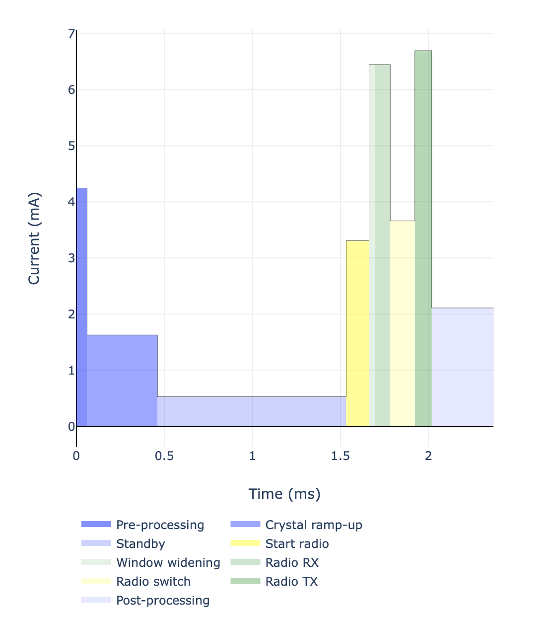
It’s been a while since I messed around with any microcontrollers and the mbed platform I used at the time has announced they’re shutting down next year. Thankfully the market has exploded since then with Micropython and Arduino supporting a wide range of different microcontrollers and lots of the native toolchains becoming considerably easier to use. Espressif ESP32 modules looked like a great option to start with, but having got a bit carried away with an order from PiHut I bought a few different modules to experiement with, including a Seeed Studio XIAO nRF52840 based on a Nordic nRF528440 µC. Nordic’s Online Power Profile suggests that configured as a Bluetooth Low Energy peripheral, the nRF52840 could idle at a slightly higher 2.7µA, but draw < 7mA during radio Rx and Tx, with each radio event taking under a millisecond. Overall, wake, transmit, sleep should take around 2.5ms. This requires an overall average current of 49µA if sampling at 10Hz (100ms interval), up to 460µA at 100Hz (10ms).

The answer to question 1 looks positive; it might well be possible to harvest sufficient energy.
Question 2 is in danger of exposing my naîvity. The nRF52840 ADC can be configured with an acquisition time as low as 2µs. My initial thought process is that a digital out pin could trigger a transistor or three to switch the CT from energising the power supply capacitors to a burden resistor, read the ADC across the burden and then switch the CT back to a power source. I think this is going to need experimentation to confirm one way or the other.
Finally, question 3 is back in my comfort zone. With the selection of µC boards I’ve collected, I’ve written some basic code to communicate back and forth, triggering a DIO to illuminate an LED when the TX or RX event occurs. Hook up an oscilloscope to the LEDS and time between the edges. Results in the next post.