Engineering notebook
Using the Seeed Studio XIAO RS485 breakout for a Modbus prototype
Notes from prototyping Modbus RTU with a Seeed XIAO RS485 breakout and an Eastron SDM120, including a working Arduino sketch.
- Published
- Projects
- Modbus Anywhere
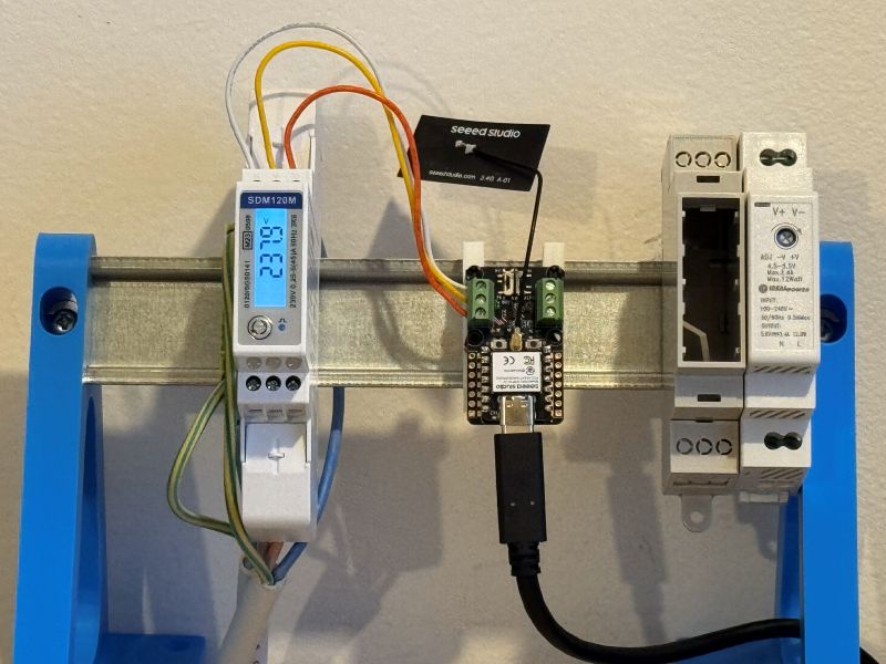
I want to get an ESP32 talking to an Eastron SDM120 electric meter. Ultimately, I plan to design a PCB to fit inside a single DIN module enclosure to keep things all nice and tidy, but wanted to experiment with a prototype before disappearing off down that particular rabbit hole. I’ve been playing with a few Seeed Studio XIAO modules for various experiments and discovered that they have an RS485 breakout which is perfect. Combined with a couple of 3D printed DIN rail mounts I was able to set it up on a test rail on the desk and wire it up to a spare SDM120.
I also decided to use this as an opportunity to start using Espressif’s ESP-IDF development environment as it has a Modbus library, along with an MQTT Client and HTTP Server with a RESTful API example which will support the next phase of experimentation. Alas, my first attempts were scuppered - timeouts reading the Voltage input register from the meter. I was pretty sure I was probably failing to set up the UART and enable pins correctly, so before resorting to a scope to check what’s actually happening on the bus, I thought I’d try falling back to an Arduino sketch to see if that would simplify matters, then being able to reference the sample code on the RS485 breakout wiki page.
This initially seemed like a bad idea as the ArduinoModbus library depends on ArduinoRS485 which in turn doesn’t support the ESP32 architecture. Googling whether I could work around the compilation problems, before finding ModbusMaster, I found this ESP32 with Modbus RTU RS485 Protocol using Arduino IDE tutorial which uses the SoftwareSerial library. This code was simple enough to adapt to use the HardwareSerial setup from the breakout wiki sample code. The only slight wrinkle was that the breakout appears to have only a single enable pin, not a separate Driver Enable and Receive Enable pins. I took a punt that this means the breakout drives both pins of the RS485 transceiver from the same ESP32 pin. Once flashed, I started getting the raw bytes of the response message written to the serial monitor and plugged them into a floating point converter to figure out the endianness and started seeing the right sort of values. After a little tidying up, this sketch was happily polling the SDM120 for the voltage and writing the parsed value to the serial monitor.
#define RE D2

// Modbus RTU Request Frame (Read input register example from SDM120 datasheet)
uint8_t tx[] = { 0x01, 0x04, 0x00, 0x00, 0x00, 0x02, 0x00, 0x00 };
uint8_t rx[9];

HardwareSerial mod(1);

void setup() {
  Serial.begin(115200);
  mod.begin(9600, SERIAL_8N1, D5, D4);
  pinMode(RE, OUTPUT);

  // Calculate CRC for the Modbus request
  uint16_t crc = calculateCRC(tx, 6);
  tx[6] = crc & 0xFF;  // CRC Low Byte
  tx[7] = crc >> 8;    // CRC High Byte
}

void loop() {
  sendModbusRequest();
  readModbusResponse();
  delay(5000);
}


void sendModbusRequest() {
  digitalWrite(RE, HIGH);
  mod.write(tx, sizeof(tx));
  mod.flush();  // Wait for transmission to complete
  digitalWrite(RE, LOW);
}

void readModbusResponse() {
  unsigned long startTime = millis();
  uint8_t index = 0;

  // Read response with 1-second timeout
  while (millis() - startTime < 1000) {
    if (mod.available()) {
      rx[index++] = mod.read();
      if (index >= 9) break;  // Full response received
    }
  }

  // Process valid response
  if (index >= 5) {  // Minimum valid frame length
    if (validateCRC(rx, index)) {
      printReceivedData();
    } else {
      Serial.println("CRC Error!");
    }
  } else {
    Serial.println("Timeout Error!");
  }
}

void printReceivedData() {
  // Print raw bytes of response
  for (int i = 0; i < 9; i++) {
    Serial.print(rx[i], HEX);
    Serial.print(" ");
  }

  // Print value parsed as IEEE-754 float
  float f;
  unsigned long *l = (unsigned long *)&f;
  *l = (unsigned long)rx[3] << 24 | rx[4] << 16 | rx[5] << 8 | rx[6];
  Serial.print(f);
  Serial.println("V");
}

// CRC Calculation Function (Modbus RTU Standard)
uint16_t calculateCRC(uint8_t *data, uint8_t length) {
  uint16_t crc = 0xFFFF;
  for (uint8_t pos = 0; pos < length; pos++) {
    crc ^= (uint16_t)data[pos];
    for (uint8_t i = 8; i != 0; i--) {
      if ((crc & 0x0001) != 0) {
        crc >>= 1;
        crc ^= 0xA001;
      } else {
        crc >>= 1;
      }
    }
  }
  return crc;
}

// CRC Validation Function
bool validateCRC(uint8_t *data, uint8_t length) {
  if (length < 2) return false;
  uint16_t receivedCRC = (data[length - 1] << 8) | data[length - 2];
  uint16_t calculatedCRC = calculateCRC(data, length - 2);
  return (receivedCRC == calculatedCRC);
}
1 4 4 43 6C CC CD BA 88   236.80V
1 4 4 43 6C CC CD BA 88   236.80V
1 4 4 43 6D 4C CD 8A 88   237.30V
1 4 4 43 6D 66 66 D4 57   237.40V
1 4 4 43 6D 4C CD 8A 88   237.30V
1 4 4 43 6D 4C CD 8A 88   237.30V
1 4 4 43 6D 80 00 1E 1D   237.50V
1 4 4 43 6D 4C CD 8A 88   237.30V
1 4 4 43 6D 19 9A F4 26   237.10V
1 4 4 43 6D 00 00 7F DD   237.00V
1 4 4 43 6D 33 33 2B 38   237.20V
1 4 4 43 6D 33 33 2B 38   237.20V
1 4 4 43 6D 19 9A F4 26   237.10V
1 4 4 43 6D 4C CD 8A 88   237.30V
1 4 4 43 6D 66 66 D4 57   237.40V
1 4 4 43 6D 33 33 2B 38   237.20V
Having now proven out the wiring of the RS485 bus and the pin allocation for the UART TX/RX and DE/RE pins I was able to revisit my abandoned attempt in ESP-IDF and got that approach working too. I’ll follow up with another post when I’ve made some more progress with the planned experiment.